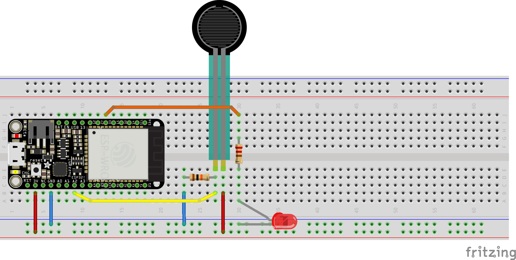
In a previous lab we covered how to use an Analog Input to control the brightness of a PWM Output, where a higher number from the Analog Input results in higher duty cycle / a brighter LED. What if we want the opposite effect: a higher number from the Analog Input results in a dimmer LED? In order to do so we will need to use linear interpolation.
Linear Interpolation
Linear Interpolation is the estimation of an unknown value that falls within two known values. If we have some input value inputValue, and we know that inputValue will be between inputMin and inputMax, we can calculate the relative position of inputValue between the new values outputMin and outputMax. In other words
outputValue = (inputValue - inputMin) * (outputMax - outputMin) / (inputMax - inputMin) + outputMin
Lets define (def) a function (called convert) to test
def convert(inputValue, inputMin, inputMax, outputMin, outputMax):
    outputVal = (inputVal - inputMin) * (outputMax - outputMin) / (inputMax - inputMin) + outputMin
    return outputVal
Now let's try converting a known number from one range to another
for i in range(10):
    print(i, convert(i, 0, 10, 0, 500))
One small adjustment: running the above code results in a floating point output. If we simply adjust the function definition to use // instead of / we can force an integers at the output
def convert(inputValue, inputMin, inputMax, outputMin, outputMax):
    outputVal = (inputValue - inputMin) * (outputMax - outputMin) // (inputMax - inputMin) + outputMin
    return outputVal
Test one more time to proove integer output:
for i in range(10):
    print(i, convert(i, 0, 10, 0, 500))
Linear Interpolation for PWM Outputs
Wire up an Analog Input and PWM Output as shown below

And let's run the following on our ESP32
# analog in to pwm out

from machine import ADC, Pin, PWM
from time import sleep_ms

ledPin = Pin(27)
potPin = Pin(34)

pot = ADC(potPin)
pot.atten(ADC.ATTN_11DB)
pot.width(ADC.WIDTH_10BIT) # 0 - 1023

pwm = PWM(ledPin, freq=20000, duty=0)

while True:
    sensor_val = pot.read()
    print(sensor_val)
    pwm.duty(sensor_val)
    sleep_ms(20)
Now, let's add the convert function and rewrite the above so a higher Analog Input value results in a lower PWM duty cycle
# analog in to pwm out

from machine import ADC, Pin, PWM
from time import sleep_ms

def convert(inputVal, inputMin, inputMax, outputMin, outputMax):
    outputVal = (inputVal - inputMin) * (outputMax - outputMin) // (inputMax - inputMin) + outputMin
    return outputVal

ledPin = Pin(33)
potPin = Pin(34)

pot = ADC(potPin)
pot.atten(ADC.ATTN_11DB)
pot.width(ADC.WIDTH_10BIT) # 0 - 1023

pwm = PWM(ledPin, freq=20000, duty=0)

while True:
    sensorVal = pot.read()
    mapVal = convert(sensorVal, 0, 1023, 1023, 0)
    print(sensorVal, mapVal)
    pwm.duty(mapVal)
    sleep_ms(20)
Add a second LED to your breadboard and try the following, in which one Analog Input controls two PWM Outputs in opposite orientations
# analog in to pwm out

from machine import ADC, Pin, PWM
from time import sleep_ms

def convert(inputVal, inputMin, inputMax, outputMin, outputMax):
    outputVal = (inputVal - inputMin) * (outputMax - outputMin) // (inputMax - inputMin) + outputMin
    return outputVal

led1Pin = Pin(27)
led2Pin = Pin(33)
potPin = Pin(34)

pot = ADC(potPin)
pot.atten(ADC.ATTN_11DB)
pot.width(ADC.WIDTH_10BIT) # 0 - 1023

pwm1 = PWM(led1Pin, freq=20000, duty=0)
pwm2 = PWM(led2Pin, freq=20000, duty=1023)

while True:
    sensorVal = pot.read()
    mapVal = convert(sensorVal, 0, 1023, 1023, 0)
    print(sensorVal, mapVal)
    pwm1.duty(sensorVal)
    pwm2.duty(mapVal)
    sleep_ms(20)