A voltage divider is a circuit that produces an output that is smaller than its input (where the output is voltage or current).

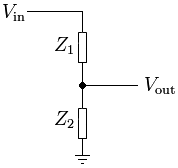
The above schematic represents the most basic way to use two resistors (labeled as Z1 and Z2) to take some voltage (Vin) and output a fraction of it (Vout). The amount of Vin that is output at Vout depends on the values of the two resistors. This is the basic wiring pattern for almost any analog sensor, btw.
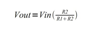
If you need to calculate the value of R1 and R2 (fyi: in this case, I am using Z and R interchangeably, but Z refers to impedance and R refers to resistance) such that you can get a specific Vout, here is the formula:

Voltage Dividers = Sensors (Sometimes!)
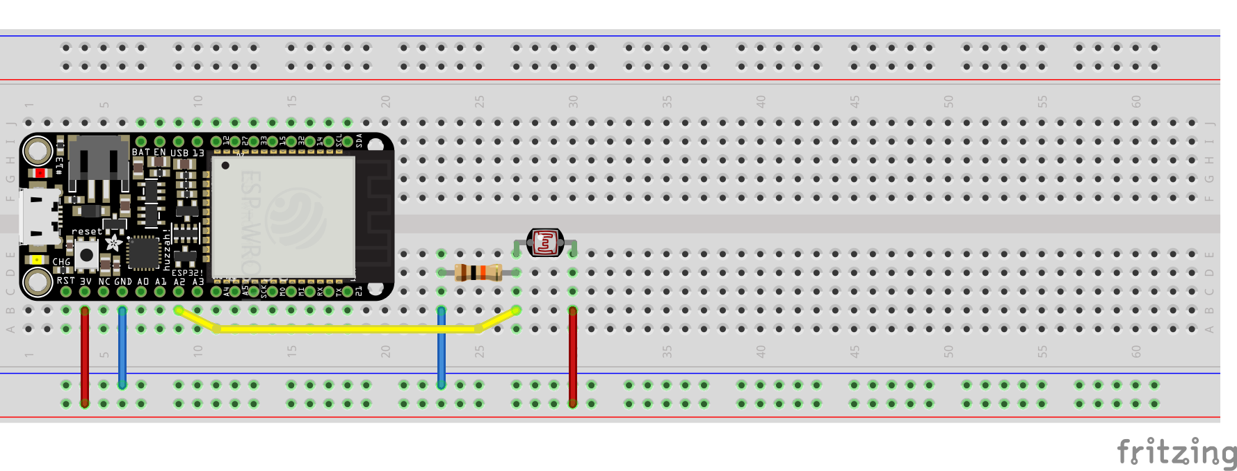
Hookup Pattern

- Connect LDR Pin1 (
Z1in Voltage Divider schematic above) to ESP323V - Connect LDR Pin2 to ESP32
34 - Connect Resistor Pin2 (
Z2in Voltage Divider schematic above) to ESP32GND
There are a collection of voltage divider-based sensors that can be used interchangeably, from a hardware and software standpoint, for wildly different interactions. To name only a few:
- Light-dependent resistor
- Force-sensitive resistor, available in a variety of shapes.
- Flex Sensor